Welcome to My Projects Page
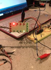
Name Badge with Stumble meter
Objective 1-A
Design and complete robotic and enbedded systems solutions that apply to real-world situations and challenges
Description
This name badge displays your name with a cool larson scan LED light display. It also uses a Gyro scope inside that trackes your movements. If you get off balance and are stumbling around it can detect this and send an email to someone to come help you.
GITHUB Link to codeLED Larson Scan Name Badge
Wire Diagram
LED Larson Scan Name Badge
Click to return to Objectives Page
IOT Light Switch
Objective 1-B
Design and complete robotic and enbedded systems solutions that apply to real-world situations and challenges
Description
This IOT light switch has its own web page hosted by the ESP 32 micro controller. It allows you to turn your dorm lights on and off from your smart phone anywhere on campus.
GITHUB Link to codeIOT Light Switch
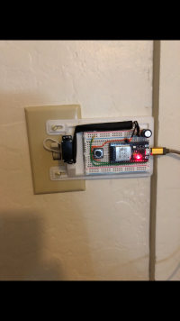
Wire Diagram
IOT Light Switch
Click to return to Objectives Page
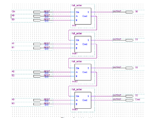
Full Adder
Objective 2-A
Implement a simple microprocessor using digital logic design
Description
A full adder is a digital circuit that performs addition. Full adders are implemented with logic gates in hardware. A full adder adds three one-bit binary numbers, two operands and a carry bit. The adder outputs two numbers, a sum and a carry bit. The term is contrasted with a half adder, which adds two binary digits.
Full Adder
Wire Diagram
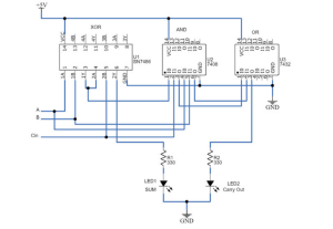
Full Adder XOR
Click to return to Objectives Page
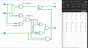
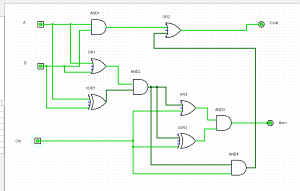
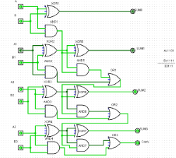
4 bit Adder
Objective 2-B
Implement a simple microprocessor using digital logic design
Description
The 4-bit adder I researched uses a one-half adder and three full adders to compute the two 4-digit binary numbers together and will have a carryout put that is the overflow. Each adder uses two regular inputs, A and B, with the carry from the previous adder as a third input. The 4-bit adder I researched and built computes the two 4-digit binary numbers threw a series of seven XOR gates, seven AND gates, and 3 OR gates resulting in the final output of the two 4- digit binary numbers computed and added together.
4 Bit Adder-1110
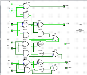
Wire Diagram
4 Bit Adder-00111
Click to return to Objectives Page
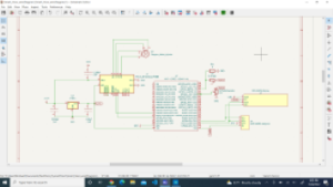
PCB board for the Robot Arm
Objective 3-A
Demonstrate embedded system design skills, including, but not limited to, microcontroller selection, schematic design, printed circuit board layout, design for electromagnetic compatibility and design for manufacturing
Description
This is a PCB board that I designed that will control a 3DOF robot arm. It has four different voltage circuits for the different servos used and a Atmega 328pb logic chip on it.
GITHUB Link to codeVirtual PCB Board design
Wire Diagram
Circuit Board
Click to return to Objectives Page
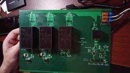
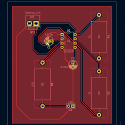
555 Timer PCB Board
Objective 3-B
Demonstrate embedded system design skills, including, but not limited to, microcontroller selection, schematic design, printed circuit board layout, design for electromagnetic compatibility and design for manufacturing
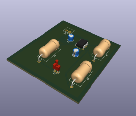
Description
This PCB board is for the 555 timer IC. It will flip flop states and blink an LED depending on the size of the capacitors connected to it. It is all done through a series of resistors, transistors, and voltage dividers, inside the IC, that monitor the voltages. Once the voltage drops low enough it flip flops the circuit to the higher voltage till that capasitor discarges then flops back.
555 3D View
555 Timer Wire Diagram
555 PCB Layout
Click to return to Objectives Page
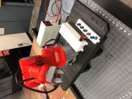
Robot Arm
Objective 4-A
Apply knowledge of transducers, actuators and simultanous hardware and software development in the design of an embedded system
Description
This is a 3DOF robot arm. It has manual control usign potentiometers or a automatic mode that will follow a set of commands to operater the arm. It was used for placing a hot dog onto a conveyor belt.
GITHUB Link to codeRobotic ARM
Wire Diagram
Robotic ARM with conveyor belt
Click to return to Objectives Page
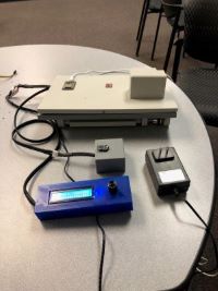
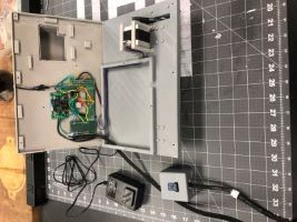
Smart Visor
Objective 4-B and Objective 5-A
Obj 4-B: Apply knowledge of transducers, actuators and simultanous hardware and software development in the design of an embedded system
Obj 5-A: Design and anallyze real-time embedded systems, including advanced digital logic design, signal processing and high-speed digital systems
Description
The Smart Visor consists of the current style sun visor in your everyday car. It will have a motor attached to it that is controlled by a microcontroller. It will take inputs from three sensors, a photoresistor, a compass, and a clock. Using these inputs, it will be able to determine the car’s directional heading, combined with the time of day(Sunrise and Sunset) it will lower the visor to protect the driver's eyes from the sunlight. It will also be able to lower the visor if there is only an increase in light levels if it is outside of the sunrise and sunset time frame.
Innovation Claim
This project is innovative because it takes the regular sun visor from a vehicle and turns it into a smart visor by incorporating a microcontroller that uses inputs from three sensors to autonomously adjust the sun visor for the driver. This improves safety by allowing for more hands-free driving and improved visibility for the driver.
GITHUB Link to codeSmart Visor
Wire Diagram
Circuit Board
Click to return to Objectives Page
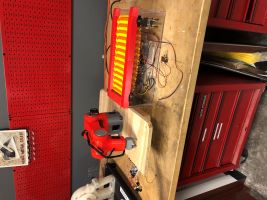
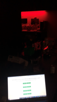
IOT LED Light strips
Objective 5-B
Design and anallyze real-time embedded systems, including advanced digital logic design, signal processing and high-speed digital systems
Description
This is an IOT controlled LED light strip that is in the engineering lab. It hosts its own web page and allows you to control three different Lighting features through the web page.
GITHUB Link to codeIOT Lights Red
Wire Diagram
IOT litghts Blue
Click to return to Objectives Page
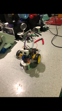
Smart CAR with Object Detection
Objective 6-A
Implement and evaluate algorithms and methods enabliing autonomy in a mobile robot
Description
This is a fully autonomous car that uses a Arduino Uno as its brain to control the drive motors and an ultra sonic sensor that allows it to see. Once an object is detected in fornt of its selve it will back up and use a servo to turn the ultra sonic sensor left and right to find a clear path to turn to.
GITHUB Link to codeObject Detection Car side view
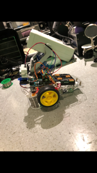
Wire Diagram
Object Detection Car front view
Click to return to Objectives Page
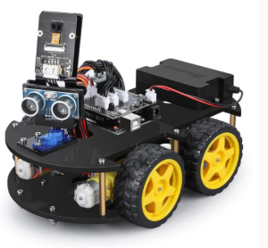
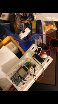
Smart CAR
Objective 6-B
Implement and evaluate algorithms and methods enabliing autonomy in a mobile robot
Description
This is a smart car made by Elegoo that can perform obstacle avoidance, line tracking, IR remote control, and Blue tooth phone App control with a ESP32 cam and ultra sonic sensor.
GITHUB Link to codeSmart Car
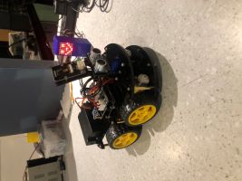
Wire Diagram
Elgoo Smart Car